Wednesday, July 24, 2013

Quality of Service (QoS) Congestion-Avoidance Notes

Congestion-avoidance tools are complementary to, and dependent upon, queuing algorithms. Queuing/scheduling algorithms manage the front of a queue, while congestion-avoidance mechanisms manage the tail of a queue.

Congestion-avoidance tools are designed for TCP traffic, because TCP has built-in flow-control mechanisms that operate by gradually increasing traffic flows until packet loss has occurred.  Once packet loss has occurred, the transmission rate is reduced before slowly ramping up again.  This means that if no mechanism is in place to control TCP, any particular flow has the ability to eat up all available bandwidth.

When there are no congestion-avoidance tools in place, and queues fill, tail drop occurs, which means all traffic is dropped. 

In a constricted channel without congestion-avoidance tools, TCP connections eventually synchronize with each other – they ramp up together, lose packets together, and back off together.  This is called global synchronization and basically results in “waves” of TCP traffic.

Congestion-avoidance tools has no real benefit or use for UDP traffic, because UDP traffic does not have any retry logic.

Random Early Detection (RED)

RED combats global synchronization by preemptively and randomly dropping packets before queues fill.  Instead of waiting for the queues to fill, RED causes the router to monitor the buffer depth and perform early drops on random packets when the defined minimum queue threshold has been exceeded.

RED drops occur within the bounds of TCP retry timers, which slows the transmission rate of sessions but prevents them from starting slow.  This optimizes network throughput.

It should be noted that Cisco IOS doesn’t support RED, only Weighted RED (WRED).  When you utilize the random-detect command in a queue, it actually enables WRED.  However, if there are no separate IPP or DSCP markings within a given class of traffic, then the effective policy is simply RED.

Weighted Random Early Detection (WRED)

WRED is an enhancement to RED that allows you to control how packets are selected to be “randomly” dropped.  A configured minimum threshold determines when packets of a given IPP value begin to be dropped.  The configured maximum threshold determines at what queue depth that all packets of that value will be dropped. The mark probability denominator determines how aggressively that packets of a given IPP value are dropped.  For example, a denominator of 10 means that up to 1 of every 10 packets will be randomly dropped for that IPP value.  The maximum rate of 1 out of every 10 packets being dropped in this example occurs at the configured maximum threshold.  Past the maximum threshold, all packets of that value are dropped (tail drop).

By default, packets with lower IPP values are dropped sooner than packets with higher IPP values. Also, WRED is dependent on queuing, so a queuing option (usually either bandwidth or fair-queue) has to be enabled on the traffic class before you can utilize WRED.

DSCP values can also be used, and this is simply called DSCP-Based WRED.  It pretty much works the same way.  It uses AF drop-preference values (the second digit in the AF code, ex: In “AF21”, the “1”) to determine what packets will be dropped. For example, when WRED is enabled on an interface, packets with a higher drop precedence value, i.e. “AF23” would be dropped more often than those with lower drop precedence values, i.e. “AF21”.

Explicit Congestion Notification (ECN)

Traditionally, the only way to inform sending hosts that there was congestion on the network so they would slow their transmission rates was to drop TCP packets.  ECN was developed to combat this by marking the final 2 bits of the Type of Service (ToS) byte of the IP header.  These two bits are:

  • ECN-Capable Transport (ECT) bit – indicates whether ECN is supported on the device
  • Congestion Experienced (CE) bit – used in tandem with the ECT bit to signal that congestion was experienced en route.

When congestion occurs WRED drops packets when the configured threshold value is exceeded.  ECN is an extension to WRED, in that ECN marks packets instead of dropping them to communicate the existence of congestion.  Routers configured with the WRED ECN feature (Introduced in IOS 12.2(8)T), use this marking to know that the network is congested.  This allows TCP to be controlled  without dropping packets or at least with dropping fewer packets.

WRED ECN takes the following actions based on the bit settings:

  • If the number of packets in a queue are below the configured threshold, packets are transmitted (Normal operation).
  • If the number of packets is between the configured minimum and maximum thresholds:
    • If ECT – 1, CE – 0  or ECT – 0, CE – 1 and WRED determines packet should be dropped based on drop probability, the ECT and CE bits are changed to 1 and the packet is transmitted.
    • If ECT and CE bits are 0, this indicates that the sending device is not capable of ECN and the packet then can be dropped based on WRED drop probability.
    • If both ECT and CE bits are set to 1, the packet indicates that there is network congestion, the packet is transmitted and no further marking is required.
  • If the number of packets in the queue is above the maximum threshold, all packets are dropped.

Dynamic Buffer Limiting (DBL)

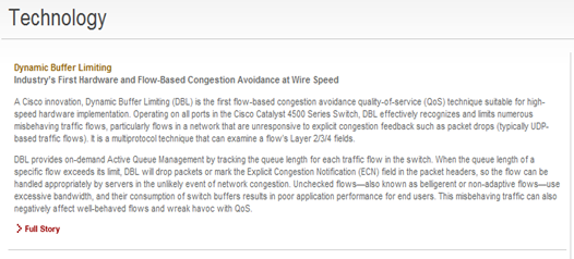
This was actually something I didn’t find out about until we started figuring out how to do QoS on a Catalyst 4500.  I went digging on Cisco’s website and from what I saw initially seemed like it was pretty awesome:

image

Industry’s First! Cisco innovation! High-speed hardware implementation!  Of course I want more info, so I clicked on Full Story:

image

Bummer – guess it can’t be found on the Kanye West - I mean cambeywest website.  Even putting in “Dynamic Buffer Limiting” into the search box on Cisco.com came up with nothing. On to Google….

Active Queue Management (AQM), which informs you of congestion before you run into a buffer overflow situation, utilizes DBL to track the queue length for each traffic flow. DBL tracks the queue length for each traffic flow in a switch.  When the queue length exceeds its limit, DBL drops packets or sets the ECN bits in the packet headers.

DBL classifies flows into two categories:

  • adaptive – reduce the rate of packet transmission once it receives congestion notification
  • aggressive – do not take any corrective action in response to congestion notification

For every active flow, the switch maintains two parameters - “buffersUsed” and “credits”.
Friday, July 19, 2013

Quality of Service (QoS) Congestion Management Notes

Of all the tools within the QoS toolset, congestion management tools, also known as queuing tools, provide the biggest impact on application service levels.  Whenever packets enter a device faster than can exit it, congestion exists and this is where queuing tools come into play.  Queuing tools are only engaged when congestion exists, otherwise packets are sent as soon as they arrive.  When congestion does exist, packets must be buffered, or queued, to mitigate dropping.

Packet markings, or lack thereof, affect queuing policies, so queuing policies are complementary and have a dependence on classification and marking policies.

Scheduling vs. Queuing

These two terms are often incorrectly used interchangeably – they are two different things.  Scheduling determines how a frame or packet exits a device. Whenever packets enter a device faster than they can exit it, as is the case with speed mismatches (ex. Gigabit Ethernet traffic heading to a WAN interface), congestion can occur.  Devices have buffers that allow the temporary storing and subsequent scheduling of these backed-up packets, and this process is called queuing.

Inbound traffic > Queuing (During congestion) > Scheduling > Outbound traffic

  • Queuing – orders packets in linked output buffers. Only engaged when there is congestion
  • Scheduling – decides which packet to transmit next.  This occurs whether there is congestion or not (Although the scheduling decision is of course much simpler when there is no congestion).

During congestion, the scheduler has to make a decision of what queue to service first based on various types of scheduling logic algorithms:

  • Strict Priority – Lower-priority queues are served only if higher-priority queues are completely empty.  This can potentially starve out lower priority queues. Strict priority is good for real-time, delay-sensitive traffic.
  • Round-robin – Services queues in a sequence.  Doesn’t have the potential to starve traffic, but may not provide the level of service that delay-sensitive traffic needs that Strict Priority scheduling would be able to provide.
  • Weighted-fair – Packets in queues are weighted so that some queues are serviced more frequently than others.  Addresses the cons of strict priority and round-robin, but doesn’t guarantee the bandwidth that real-time flows may require.

Congestion Management vs. Congestion Avoidance

The amount of buffer space (memory) for queues is of course limited.  Once the buffer is overrun, packets may be dropped as they arrive (tail drop), or proactively beforehand.  The selective, proactive dropping of packets is called congestion avoidance.  Congestion avoidance works best with TCP-based applications since the selective dropping causes the TCP windowing mechanism to engage and throttle back the rate of traffic flow to a manageable state.  The relationship between this and congestion management is that the scheduling algorithms of congestion management manage the front of a queue, where with congestion avoidance, the mechanisms manage the tail of a queue.

Legacy L3 Queuing Mechanisms

These are considered legacy, but are what newer mechanisms are built upon:

  • Priority queuing (PQ)
  • Custom queuing (CQ)
  • Weighted Fair Queuing (WFQ)

Newer queuing mechanisms used combinations of these while also attempting to minimize drawbacks, such as:

  • Class-based Weighted Fair Queuing (CBWFQ)
  • Low latency queuing (LLQ)
Priority Queuing
  • Only consists of 4 queues (high, medium, normal/default, low)
  • Scheduler empties high queue first before servicing lower queues.
    • So, similar to strict priority queuing, handles real-time traffic well but risks starving other queues.
Custom Queuing
  • Introduced a round-robin scheduler based on byte counts.
    • Prevented bandwidth starvation and introduced bandwidth guarantees
  • Supports up to 16 queues
  • No capability to provide strict priority
Weighted Fair Queuing
  • Built to expand upon principle of fairness that CQ introduced
  • Simply divided interface bandwidth by number of flows
  • Added a fixed weight based on IPP for bandwidth calculation to favor higher-priority flows, based on that IPP marking
  • No ability to provide bandwidth guarantees due to bandwidth allocation changing as flows are added and ended

Currently Recommended L3 Queuing Mechanisms

Enhanced mechanisms were developed to utilize the strengths of the legacy mechanisms while minimizing their weaknesses.

Class-Based Weighted Fair Queuing
  • Hybrid queuing algorithm that combines guaranteed bandwidth (from CQ) with the ability to dynamically ensure fairness to other flows within a class of traffic (from WFQ)
  • Up to 256 classes of traffic with reserved queues
    • Each queue is serviced based on assigned bandwidth
      • Minimum bandwidth is explicitly defined and enforced
  • Uses Modular QoS CLI (MQC)-based class maps for classification

CBWFQ lacks the ability to provide strict-priority queuing for real-time applications.  To service real-time applications, a strict-priority queue was added to the CBWFQ algorithm, and low-latency queuing (LLQ) was born.

Low Latency Queuing
  • Enhanced combination of PQ, CQ, and WFQ.
  • Basically CBWFQ with a strict PQ.
  • Has a built-in policer to to prevent the strict-priority queue from starving lower-priority traffic
    • Only engages when there is congestion, so it is important to provision priority classes properly
Bandwidth Provisioning in LLQ
  • General best practice is to provide at least 25% of a link’s bandwidth to class-default
  • Limit the sum of all priority class traffic to no more than 33% of a link’s capacity.
  • All bandwidth guarantees within LLQ should be no more than 75% link capacity.
    • When the percentage-remaining (bandwidth remaining percent) form of LLQ is used, this rule goes out the window because it utilizes a percentage of the remaining bandwidth after the PQ is serviced rather than a set value.

Quality of Service (QoS) Classification and Marking Notes

The first part of building a QoS policy is to identify the traffic that you need to treat preferentially (give better priority), or differentially.  This is accomplished via classification and marking.

  • Classification – sorts packets into different traffic types that policies can then be applied to.
  • Marking (or re-marking) – establishes a trust boundary on which scheduling tools later utilize.  The edge of the network where markings are either accepted or rejected is known as the trust-boundary.
  • Classifier tools – Inspect one or more fields in a packet to identify the type of traffic that is being carried. After being identified, it is passed to the appropriate mechanism to handle that type of traffic class.
  • Marking tools – actually write a field within the packet (or frame, cell, label) to preserve the classification decision.  By marking traffic at a trust boundary, subsequent nodes do not have to perform the same in-depth analysis to determine how to treat the packet.

Classification Tools

These tools can examine a number of criteria within layers 1, 2, 3, 4, and 7.

  • L1 – Physical interface, subinterface, PVC, port
  • L2 – MAC, 802.1Q/p CoS, VLAN, MPLS EXP, ATM Cell Loss Priority (CLP), Frame Relay DE
  • L3 – IPP, DSCP, source/dest IP address
  • L4 – TCP/UDP Ports
  • L7 – Application signatures and URLs in packet headers or payload

Marking Tools

The primary marking tools used currently are class-based marking and marking done via class-based policing.  Legacy marking techniques include committed access rate (CAR) and policy-based routing (PBR).  Voice gateway packet marking is also an option for IPT applications.

  • L2 Marking Fields – 802.1Q/p CoS, MPLS EXP, ATM CLP, Frame Relay DE
  • L3 Marking Fields – IPP or DSCP

Cisco Catalyst switches perform scheduling based on L2 CoS, however DSCP is the preferred marking method for end-to-end QoS, because L2 marking is lost whenever the L2 media changes.  So it is important to ensure that L2 markings are translated to and from L3 markings consistently throughout the environment for end-to-end QoS.

Saturday, July 13, 2013

Optimizing and Protecting Spanning Tree – Lab Testing

Unfortunately the equipment I was using didn’t support PVST+ (Sup2Ts in 6503 Catalyst Switches), so I skipped testing UplinkFast and BackboneFast as these are incorporated in 802.1w (RSTP) and 802.1s (MSTP, which is basically an extension of RSTP).

BPDU Guard

image

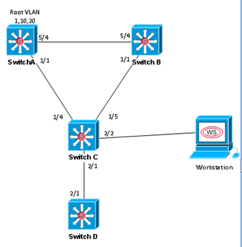
For this test, SwitchD will be treated as a Rogue Switch being attached to the network.  Initially, SwitchC’s port 2/1 is configured as an access port with only PortFast enabled.

  1. 1. Disconnect link between SwitchC and SwitchD
  2. 2. Configure SwitchC port 2/1 as an access port in VLAN 10 with PortFast enabled.
  3. 3. Configure SwitchD port 2/1 as an access port in VLAN 10. Configure the priority on VLAN 10 to be 0.
  4. 4. Reconnect link between SwitchC and SwitchD and check topology for VLAN 10. SwitchD should be the root for VLAN 10.
  5. 5. Disconnect link between SwitchC and SwitchD
  6. 6. Enable BPDU Guard on Switch C port 2/1
  7. 7. Reconnect link between SwitchC and SwitchD. SwitchC port 2/1 should move to an err-disable state. Verify with sh interfaces status err-disabled. Verify SwitchD is no longer the root for VLAN 10.

*Jul  5 22:02:06.023: %SPANTREE-2-BLOCK_BPDUGUARD: Received BPDU on port GigabitEthernet2/1 with BPDU Guard enabled. Disabling port.
*Jul  5 22:02:06.023: %PM-4-ERR_DISABLE: bpduguard error detected on Gi2/1, putting Gi2/1 in err-disable state

SwitchC#show interfaces status err-disabled

Port            Name               Status            Reason
Gi2/1           SWITCHD_2/1        err-disabled      bpduguard

BPDU Filtering

image

  1. Run packet capture. Verify BPDUs are seen.
  2. Configure SwitchC port 2/1 with BPDU Filter.
  3. Run packet capture. Verify no BPDUs are seen.
  4. Verify SwitchD sees itself as the root bridge for all VLANs.
  5. Remove BPDU Filter from SwitchC port2/1. Verify BPDUs are seen again.
  6. Disconnect link between SwitchC and SwitchD.
  7. Configure SwitchC port 2/1 as access port in VLAN 1 with PortFast enabled.
  8. Configure SwitchD port 2/1 as access port in VLAN 1 with BPDU Filter enabled. Verify SwitchC sees this as an Edge port.
  9. Enable BPDU Filter globally on edge ports on SwitchC. Verify no BPDUs are seen in packet capture.
  10. Disable BPDU Filter on SwitchD port 2/1. Verify switch C port 2/1 disables BPDU Filter with sh spanning-tree int gig 2/1 detail and BPDUs are seen again in packet capture.

Root Guard

Oh man, this one was a doozy.  After some digging and posting on forums, there are definitely some differences in opinion.  I saw references stating that Root Guard should be placed on all non-root ports – basically anywhere you wouldn’t expect to see the root bridge.  The CCNP SWITCH Official Cert Guide (OCG) however stated that current design practices are to place Root Guard only on access ports.  After my research and testing, I would say – it depends.

image

SwitchD will again be a Rogue Switch

  1. Disconnect link between SwitchC and SwitchD
  2. Configure SwitchD with a priority of 0 for all VLANs.
  3. Reconnect link between SwitchC and SwitchD. Verify SwitchD is the root for all VLANs.
  4. Disconnect link between SwitchC and SwitchD.
  5. Configure Root Guard on SwitchA ports 1/1 and 5/4.
  6. Reconnect link between SwitchC and SwitchD. Verify SwitchA places ports 1/1 and 5/4 in root-inconsistent state with sh spanning-tree inconsistentports. Verify Switch B and SwitchC sees SwitchD as the root for all VLANs.

*Jul 8 21:22:41.903: %SPANTREE-2-ROOTGUARD_CONFIG_CHANGE: Root guard enabled on port TenGigabitEthernet1/1.
*Jul 8 21:24:06.319: %SPANTREE-2-ROOTGUARD_BLOCK: Root guard blocking port TenGigabitEthernet1/1 on VLAN0001

SwitchA#sh spanning-tree inconsistentports
Name Interface Inconsistency
-------------------- ---------------------- ------------------
VLAN0001 TenGigabitEthernet1/1 Root Inconsistent
VLAN0001 TenGigabitEthernet5/4 Root Inconsistent
VLAN0010 TenGigabitEthernet1/1 Root Inconsistent
VLAN0010 TenGigabitEthernet5/4 Root Inconsistent
VLAN0020 TenGigabitEthernet1/1 Root Inconsistent
VLAN0020 TenGigabitEthernet5/4 Root Inconsistent
Number of inconsistent ports (segments) in the system : 6

  1. Disconnect link between SwitchC and SwitchD.
  2. Configure Root Guard on all ports you wouldn’t expect to see superior BPDUs on.
    1. SwitchB port 1/1, SwitchC port 2/1
  3. Reconnect link between SwitchC and SwitchD. Verify SwitchC places port 2/1 into root-inconsistent state. Verify SwitchA and SwitchB ports do not change.
  4. Disconnect the link between SwitchA and SwitchB. Verify SwitchB becomes isolated due to its only remaining link being placed into a root-inconsistent state.

What I discovered from this was that Root Guard worked like a charm but in one specific scenario it’s not so great.  When a link failure occurs between what would be the two distros, the only remaining path that can be utilized for convergence can’t be used because when the superior BPDUs from root hit the remaining switch uplinks that have Root Guard configured, Root Guard triggers and the ports are put into root-inconsistent, effectively breaking the network.  So this led me to believe that really, Root Guard should be kept to access ports as described in the CCNP SWITCH OCG.

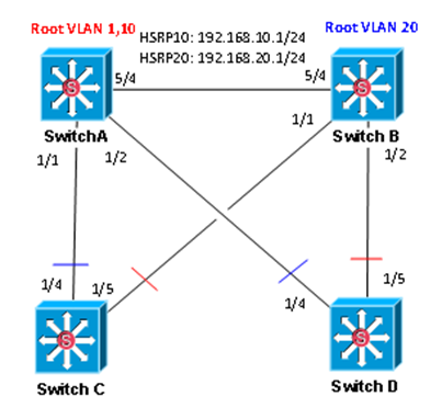
I decided to run a second, more realistic type of environment to really test this out.  I set up a pair of distro switches and access switches, and setup HSRP on the distros as well as alternating odd and even VLAN traffic between them.  The first thing I learned was not to place Root Guard on the link between the two distros – that really screws things up.  Makes sense though – I was putting it on root ports for alternating VLANs.

image

1. Configure Root Guard on SwitchA and SwitchB ports 5/4 and 1/1-2. Note the resulting spanning tree topology and HSRP status

image

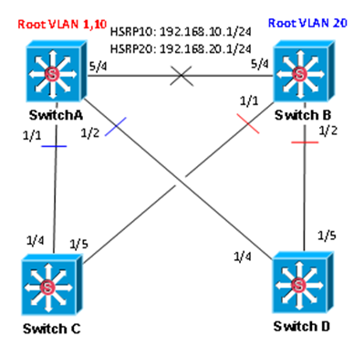
2. Remove Root Guard on SwitchA and SwitchB port 5/4. Note the resulting spanning tree topology and HSRP status

image

3. Disable link between SwitchA and SwitchB. Note the resulting spanning tree topology and HSRP status.

image 

4. Remove Root Guard from SwitchA and SwitchB ports 1/1-2. Note the resulting spanning tree topology and HSRP status.

image

To summarize all of this, it was the same story as the first test.  Root Guard works fine as long as the link between the two distros doesn’t go down.  Now, most folks run at least two links between distros so this should never happen, but for me personally, I’d avoid Root Guard on interswitch links unless a security requirement forced me to do so, or as was pointed out on a forum I frequent, a situation where you have a network you don’t control that connects to your network and that needs to participate in your STP topology.  In that case, just to protect yourself, Root Guard would be appropriate there.

But what is the point of having Root Guard on access ports if you have BPDU Guard to handle that?  Well, again – it depends.  It was said by one individual that if you have both of them enabled on an access port, Root Guard triggers before BPDU Guard.  This was eye-opening to me and sounded like a great idea.  That way you can tell if some generic switch got hooked up to the network or someone was REALLY dumb (or malicious) and hooked up a switch and attempted to hijack the current root bridge.  Turns out though that this must be code or platform specific, because I couldn’t get that to work on a 6503 with a Sup2T and 6848-GE-TX running 15.1.1.SY or a 3750X running 12.2.55.SE7.

SwitchC(config-if)#do sh run int gig 2/1
Building configuration...

Current configuration : 155 bytes
!
interface GigabitEthernet2/1
description SWITCHD_2/1
switchport
switchport mode access
spanning-tree bpduguard enable
spanning-tree guard root
end

SwitchC(config)#int gig 2/1
SwitchC(config-if)#shut
SwitchC(config-if)#no shut
SwitchC(config-if)#
*Jul 12 21:51:26.969: RSTP(1): initializing port Gi2/1
*Jul 12 21:51:26.969: RSTP(1): Gi2/1 is now designated
*Jul 12 21:51:26.973: RSTP(1): transmitting a proposal on Gi2/1
*Jul 12 21:51:26.973: RSTP[1]: Gi2/1 state change completed. New state is [blocking]
*Jul 12 21:51:27.873: %SPANTREE-2-BLOCK_BPDUGUARD: Received BPDU on port GigabitEthernet2/1 with BPDU Guard enabled. Disabling port.
SwitchC(config-if)#
*Jul 12 21:51:27.873: %PM-4-ERR_DISABLE: bpduguard error detected on Gi2/1, putting Gi2/1 in err-disable state
SwitchC(config-if)#no spann
SwitchC(config-if)#no spanning-tree bpduguar
SwitchC(config-if)#no spanning-tree bpduguard
SwitchC(config-if)#shut
SwitchC(config-if)#no shut
SwitchC(config-if)#
*Jul 12 21:51:52.577: RSTP(1): initializing port Gi2/1
*Jul 12 21:51:52.577: RSTP(1): Gi2/1 is now designated
*Jul 12 21:51:52.581: RSTP(1): transmitting a proposal on Gi2/1
*Jul 12 21:51:52.581: RSTP[1]: Gi2/1 state change completed. New state is [blocking]
SwitchC(config-if)#
*Jul 12 21:51:52.601: %SPANTREE-2-ROOTGUARD_BLOCK: Root guard blocking port GigabitEthernet2/1 on VLAN0001.
SwitchC(config-if)#
SwitchC#


3750A#sh run int gig 2/0/1
Building configuration...

Current configuration : 139 bytes
!
interface GigabitEthernet2/0/1
description 3750B
switchport mode access
spanning-tree bpduguard enable
spanning-tree guard root
end

3750A(config)#int gig 2/0/1
3750A(config-if)#shut
3750A(config-if)#no shut
3750A(config-if)#
*Mar  1 00:05:39.914: setting bridge id (which=3) prio 32769 prio cfg 32768 sysid 1 (on) id 8001.7081.05a2.ed80
*Mar  1 00:05:39.914: set portid: VLAN0001 Gi2/0/1: new port id 8037
*Mar  1 00:05:39.914: STP: VLAN0001 Gi2/0/1 -> listening
*Mar  1 00:05:41.877: %SPANTREE-2-BLOCK_BPDUGUARD: Received BPDU on port Gi2/0/1 with BPDU Guard enabled. Disabling port.
*Mar  1 00:05:41.877: %PM-4-ERR_DISABLE: bpduguard error detected on Gi2/0/1, putting Gi2/0/1 in err-disable state
3750A(config-if)#int gig 2/0/1
3750A(config-if)#no spanning
3750A(config-if)#no spanning-tree bpduguard
3750A(config-if)#shut
3750A(config-if)#no shut
3750A(config-if)#
*Mar  1 00:06:05.399: setting bridge id (which=3) prio 32769 prio cfg 32768 sysid 1 (on) id 8001.7081.05a2.ed80
*Mar  1 00:06:05.399: set portid: VLAN0001 Gi2/0/1: new port id 8037
*Mar  1 00:06:05.399: STP: VLAN0001 Gi2/0/1 -> listening
*Mar  1 00:06:07.395: %LINK-3-UPDOWN: Interface GigabitEthernet2/0/1, changed state to up
*Mar  1 00:06:07.404: STP: VLAN0001 heard root     1-c84c.75a6.fa80 on Gi2/0/1
*Mar  1 00:06:07.404:     supersedes 32769-7081.05a2.ed80
*Mar  1 00:06:07.404: %SPANTREE-2-ROOTGUARD_BLOCK: Root guard blocking port GigabitEthernet2/0/1 on VLAN0001.

After some thought, while you may not be able to run both Root Guard and BPDU Guard on the same port (effectively), there may be a use case for one or the other.  Maybe you didn’t need such a hardcore mechanism like BPDU Guard that err-disables a port upon receipt of a BPDU, but you still wanted to protect yourself at least from hijacking of the root bridge.  This is where putting Root Guard on the access port makes sense instead of BPDU Guard.  Not as secure, I know, but it’s an option.

Loop Guard Testing

image

1. Enable BPDU Filter on SwitchB port 1/1. Verify SwitchC port 1/5 transitions to forwarding.

2. Hook up workstation to SwitchC port 2/2 and generate broadcast traffic. Verify broadcast storm ensues via Wireshark.

3. Disable BPDU Filter on SwitchB port 1/1. Verify SwitchC port 1/5 resumes ALT/BLK.

4. Configure Loop Guard on SwitchC port 1/5.

5. Enable BPDU Filter on SwitchB port 1/1. Verify SwitchC port 1/5 is placed in loop-inconsistent state with sh spanning-tree inconsistentports.

SwitchC#sh span vlan 1
VLAN0001
Spanning tree enabled protocol rstp
Root ID Priority 4096
Address 0017.0f61.5281
Cost 2
Port 4 (TenGigabitEthernet1/4)
Hello Time 2 sec Max Age 20 sec Forward Delay 15 sec
Bridge ID Priority 32769 (priority 32768 sys-id-ext 1)
Address 0013.5f1c.ca40
Hello Time 2 sec Max Age 20 sec Forward Delay 15 sec
Aging Time 480
Interface Role Sts Cost Prio.Nbr Type
------------------- ---- --- --------- -------- --------------------------------
Te1/4 Root FWD 2 128.4 P2p
Te1/5 Desg BKN*2 128.5 P2p *LOOP_Inc
Gi2/1 Desg FWD 4 128.129 P2p

SwitchC#sh spanning-tree inconsistentports
Name Interface Inconsistency
-------------------- ---------------------- ------------------
VLAN0001 TenGigabitEthernet1/5 Loop Inconsistent
VLAN0010 TenGigabitEthernet1/5 Loop Inconsistent
VLAN0020 TenGigabitEthernet1/5 Loop Inconsistent

6. Disable BPDU Filter on SwitchB port 1/1. Verify SwitchC port1/5 is recovered.

This test was pretty fun – I don’t think before now I had ever purposely induced a loop.  I knew it was working when I went to do a Wireshark Packet capture and within 3 seconds or so Wireshark was locked up and eating up almost 3Gb of my memory. :)

LoopWireshark

Wednesday, July 3, 2013

Optimizing and Protecting Spanning Tree

Optimizing STP


Left to defaults, 802.1d (plain old STP) can take a very long time to converge.  For example, when a root switch fails, a switch must wait Maxage (20 seconds) before convergence can even begin.  Then, the newly forwarding ports must wait 2 x Forward Delay (15 seconds) to transition through the listening and learning states before they can begin to actually start forwarding.  This is a total of 50 seconds - a noticeable network hit.

Enhancements have been added over time to address this, such as PortFast, UplinkFast, and BackboneFast.

PortFast

This Cisco-proprietary feature allows a port to immediately transition to forwarding state once it is physically up (powered on and plugged in).  It does this by skipping the listening and learning states.  This should only be enabled on access ports.  If a switch is connected to a port with PortFast enabled, loops may occur.  For this reason, it is a good idea to enable Bridge Protocol Data Unit (BPDU) Guard and Root Guard when using PortFast.

UplinkFast


UplinkFast improves convergence by providing alternate root ports (RPs) for immediate transition in case of a failure of the current RP.  When you enable UplinkFast, three things occur:
  1. Increases root priority to 49,152
  2. Increases port costs to 3000
  3. Tracks alternate RPs which are ports that are receiving Hello messages from the root switch.
This lends itself well to good STP design with access switches - access switches should never become root or transit switches.  The increased root priority reduces the chance of the switch becoming root.  The increased port costs reduce the chance of the switch becoming a transit switch.  Lastly, when the RP fails, the switch can immediately fail over to an alternate uplink.

When a failure of the RP occurs on a switch with UplinkFast enabled, the switch immediately transitions to an alternate RP and begins forwarding.  It also sends out a multicast frame with the source MAC address of each local MAC address which causes other switches to update their Content Addressable Memory (CAM).

BackboneFast


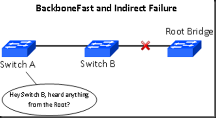
BackboneFast optimizes convergence when an indirect failure occurs.  When a direct failure occurs, such as an RP, a switch doesn't have to wait Maxage to transition (thanks to UplinkFast).  However, when an upstream link to the root fails, this causes lost Hello messages for downstream switches.  This is where these switches would have to wait Maxage before converging. BackboneFast addresses this by causing the switch to ask their neighboring switch if they are still receiving Hellos from the root.

BBFast_Indirect_Fail
 

When a Hello goes missing, a switch with BackboneFast enabled will send a Root Link Query (RLQ) BPDU out the port that the Hello should have arrived.  If the switch that receives the RLQ has a direct failure of the root, it will send a RLQ message back to the requesting switch to inform it that the path to root has been lost.  This will trigger the requesting switch to skip the Maxage timer and begin converging.  These RLQs sent back and forth of course requires that BackboneFast be configured on all switches participating.

As an interesting side note, the UplinkFast and BackboneFast features were incorporated into the 802.1w (RSTP) protocol.

Protecting STP


BPDU Guard and BPDU Filter


BPDU Guard is basically a feature to prevent a situation where good intentions can lead to network outages.  For example, just a few more ports may be needed in a meeting room, so someone goes and finds a switch (with no knowledge of how that switch operates or is configured), and attaches it to the network.  Now there is the risk of your access ports receiving superior BPDUs that cause topology changes or worse.  BPDU Guard is enabled per port and protects your access ports by disabling them upon receiving any BPDU (because we don't expect there to be any BPDUs received on access ports).  When a port is shut down (err-disabled) by BPDU Guard, configuration must occur in order to recover.  The port must be manually re-enabled or a timeout can be configured where the port will automatically recover.

BPDU Filter restricts the switch from sending BPDUs out access ports, as these would be unnecessary.  It can be enabled per-interface or globally.  When enabling BPDU Filter globally, the following occurs:
  • Filtering takes effect on all operational PortFast ports that do not have it already specifically enabled.
  • Upon startup, the port will transmit ten BPDUs. If BPDUs are seen, the port will lose its PortFast status, BPDU Filter will disable, and the port will revert to sending and receiving BPDUs like any standard STP switch port.

Root Guard


Root Guard is also enabled per port and is used to ignore superior BPDUs that would allow an attached switch to become root.  Upon receipt of a superior BPDU, the port is placed into a root-inconsistent state, and stops receiving or forwarding frames until the superior BPDUs cease. Current design practices are to place this on access ports.  Placing this on inter-switch links (trunks) could result in switch isolation when inter-switch link failures occur.

Unidirectional Link Detection (UDLD)


UDLD protects a switch trunk port from causing loops.  It does this by detecting a unidirectional link condition which can be caused by miscabling, cutting one fiber cable, unplugging one fiber, GBIC problems, etc.  Although the likelihood of this occurring in fiber connections is much greater, it can also occur in copper and UDLD handles that as well.  UDLD can be run in regular or aggressive mode.  In regular mode, L2 message is used to detect when a switch can no longer receive frames from a neighbor.  The switch whose transmit interface didn't fail is placed into an err-disabled state.  In aggressive mode, eight attempts are made to reconnect to the neighbor.  If no reply is received, both sides become err-disabled.

Loop Guard


Loop Guard is used to prevent a switch trunk port from transitioning from blocking to forwarding upon an absence of BPDUs.  The loss of BPDUs doesn't always mean a broken link - it could be degraded performance.  A port moving to forwarding could cause more damage than the absence of BPDUs itself.  Loop Guard addresses this by placing a port into a loop-inconsistent state rather than allowing it to transition to a forwarding state.

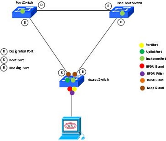
Below is a picture where these features should be placed, in my opinion.

Optimizing and Protecting Spanning Tree

Notice that Root Guard is nowhere to be found.  This is because after research and testing, it is my opinion that Root Guard should not be used unless there is a security requirement for it or a specific set of circumstances exist, such as a separate network you have no control over connecting to your network and needing to participate in your STP topology.  Root Guard in this scenario would prevent something in that network from accidentally hijacking your root bridge.