Here is the topology:
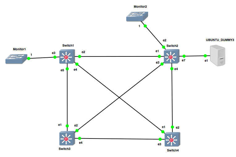
Only VLAN 1 is present on all switches and Switch1 is configured to be the primary root, while Switch2 is configured to be the secondary. Here's the current state of the network:

To review the Topology Change process when a switch detects a topology change event:
- Set tcWhile timer on all non-Edge Designated ports and Root port if it exists
- Flush MAC addresses learned on ports in step 1
- Send BPDUs with the Topology Change (TC) flag set on these ports every Hello seconds until tcWhile expires
Switch4#sh mac address-table
Mac Address Table
------------------------------------------------------------------
Vlan Mac Address Type Ports Moves Last Move
---- ----------- ---- ----- ----- ---------
1 0800.274a.33f1 DYNAMIC Et1 1 0:00:25 ago
Total Mac Addresses for this criterion: 1
We see it learned Switch2's MAC address on Et1. Vice-versa, we look at Switch2's CAM table and see it learned Switch4's MAC on Et1:
Switch2#sh mac address-table
Mac Address Table
------------------------------------------------------------------
Vlan Mac Address Type Ports Moves Last Move
---- ----------- ---- ----- ----- ---------
1 0800.277b.3066 DYNAMIC Et1 1 0:00:28 ago
Total Mac Addresses for this criterion: 1
Now, let's do the same process over again, but then shut down Et1 on Switch4. Et1 is Switch4's Root Port, so what should happen is Et2, which is an Alternate Port, should transition to a Forwarding state. This meets the criteria for a topology change event.
After we shut Et1, we take a look at the spanning tree status on Switch4:
Switch4#sh span
VL1
Spanning tree enabled protocol rapid-pvst
Root ID Priority 4097
Address 0800.2773.3845
Cost 4000 (Ext) 0 (Int)
Port 2 (Ethernet2)
Hello Time 2.000 sec Max Age 20 sec Forward Delay 15 sec
Bridge ID Priority 32769 (priority 32768 sys-id-ext 1)
Address 0800.277b.3066
Hello Time 2.000 sec Max Age 20 sec Forward Delay 15 sec
Interface Role State Cost Prio.Nbr Type
---------------- ---------- ---------- --------- -------- --------------------
Et2 root forwarding 2000 128.2 P2p
Et3 alternate discarding 2000 128.3 P2p
Et2 transitioned to a Root role, Forwarding state, which qualifies as a topology change event. Looking at the CAM table of Switch4, we see the previous entry is now gone:
Switch4#sh mac address-table
Mac Address Table
------------------------------------------------------------------
Vlan Mac Address Type Ports Moves Last Move
---- ----------- ---- ----- ----- ---------
Total Mac Addresses for this criterion: 0
Looking at Switch2, we see the previous entry is also gone as well:
Switch2#sh mac address-table
Mac Address Table
------------------------------------------------------------------
Vlan Mac Address Type Ports Moves Last Move
---- ----------- ---- ----- ----- ---------
Total Mac Addresses for this criterion: 0
Send BPDUs with the Topology Change (TC) flag set on these ports every Hello seconds until tcWhile expiresSo once Switch4 detected the topology change, it started firing off BPDUs with the TC flag bit set out its newly-elected Root Port, interface Et2.

Once a switch experiences a local topology change, or learns about one from another switch by receiving a BPDU with the TC flag set on a Root or Designated port, it too will in turn go through the same process. So let's take a look at what happened on the network holistically:

- Interface Et1 which was the Root Port for Switch4 is shut down. Switch4 had elected Et2 as an Alternate Port previously, so it immediately transitions the port to the new Root Port. This places Et2 into a Forwarding state which triggers a topology change event, so Switch4 then sets the tcWhile timer and flushes the CAM table entries learned on Et2, and begins sending BPDUs with the TC flag set out the same port. At the same time, Et3 begins receiving superior BPDUs so it is transitions from a Designated Port to an Alternate Port.
- Switch2 receives a BPDU with the TC flag set on Et4, so it sets the tcWhile timer, flushes any CAM table entries learned on, and begins sending BPDUs with the TC flag set on its Root and other Designated Port, Et1 and Et3, respectively. Ultimately, the TC BPDU sent from Et3 will be discarded upon reaching Switch3.
- Switch1 receives a TC BPDU on Et2. It sets the tcWhile timer, flushes learned CAM table entries, and sends TC BPDUs from its only other remaining active Designated Port, Et5.
- After interface Et1 on Switch4 was shut down, Switch3 began receiving what it determined to be inferior BPDUs on Et4 due to Switch4 now advertising a higher Root Path Cost (RPC), so Switch3 transitioned the port from an Alternate Port to a Designated Port. Switch3 then receives a TC BPDU on Et1, so it sets the tcWhile timer, flushes any learned CAM table entries, and sends TC BPDUs out its only other Designated Port, Et4 - which will end up being discarded.
At this point, all switches have been informed and made the appropriate changes into a new, loop-free converged topology. So that's how the topology change process is handled in RSTP!
No comments:
Post a Comment