Wednesday, March 30, 2016

Creating a Dynamic Lab Environment with vEOS and GNS3 - Part II

SETTING UP A DHCP AND FILE SERVER FOR USE WITH ZTP

Now that we have a couple vEOS instances configured and able to communicate, and we have our out-of-band network set up, we can now begin to use ZTP to provide an initial startup config.


NOTE
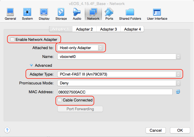
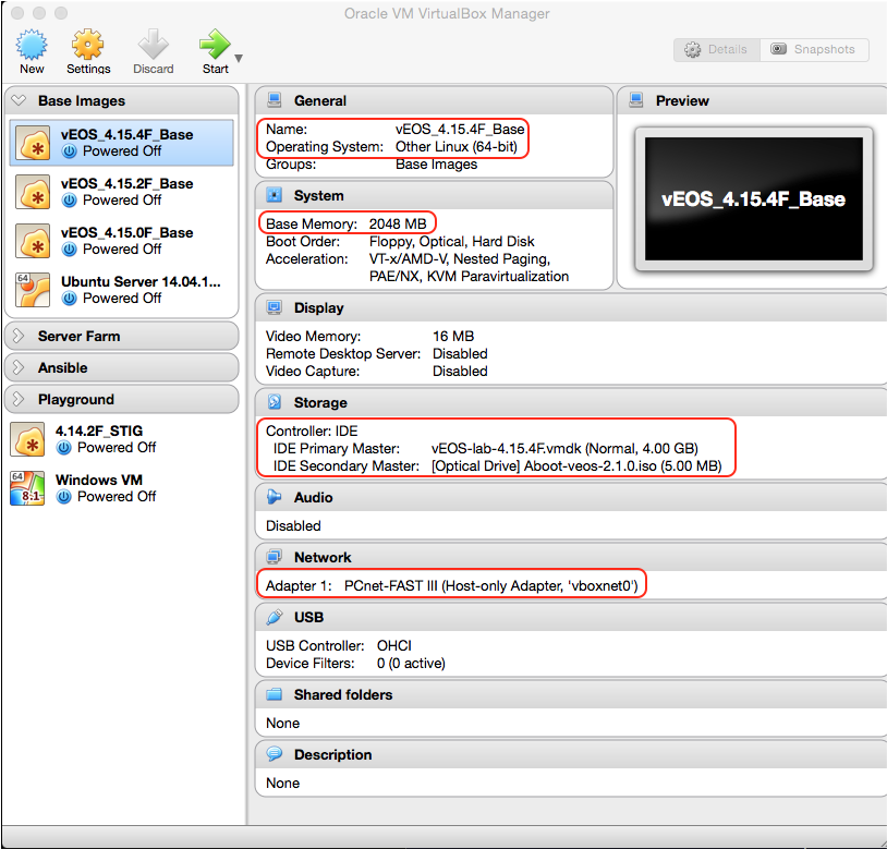
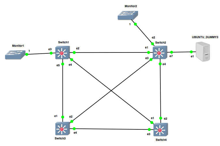
Notice that we did not connect the Management1 interface of either vEOS instance to anything inside of GNS3.  If you remember when we created the VMs, their first interface is a host-only adapter connected to the vboxnet in VirtualBox, so it’s automatically connected and there’s nothing additional we need to do there, but GNS3 doesn’t know that so it considers the interface disconnected, and that’s OK.  That saves us from having to add our management server(s) to the topology and cluttering it up (Just imagine trying to have a nice clean-looking topology in GNS3 if you had to have a connection from every vEOS instance to the management server(s) ), which is distracting and ugly - we’re better than that.


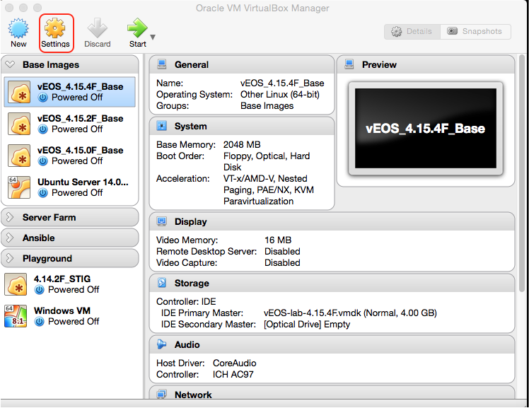
ZTP is enabled as a default on the vEOS instances, but we still need to set up a server to provide DHCP and File services.  For servers, Ubuntu is my go-to and I usually work with them in VirtualBox the same way I do with vEOS - I create a base image that is my raw golden standard and then create clones from it.


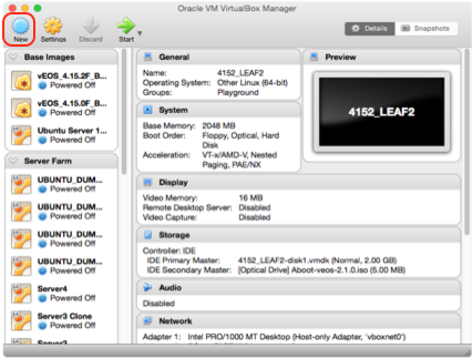
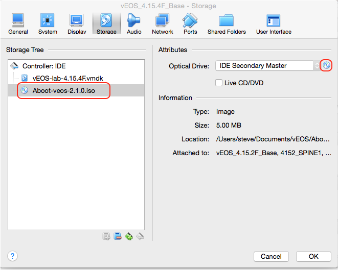
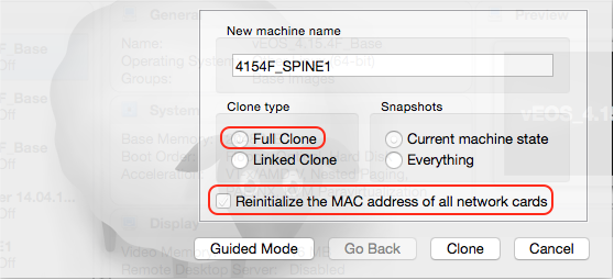
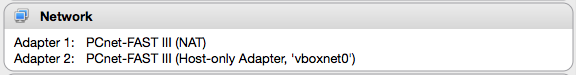
In this case, I already have a base image that is running Ubuntu Server 14.04.1 LTS, so I’ll go ahead and create a clone of that to work with.  For this server we’ll want one adapter connected to the vboxnet, and another adapter attached to NAT so that we can download and install DHCP and File services:


TIP!
Something I’ve found handy is to edit the description of my server VMs in VirtualBox to reflect what they have installed.  For example, my server base image has the following description:

BASE IMAGE - Ubuntu Server 14.04.1 LTS
==========================================
ifenslave-2.6 (NIC Bonding, LACP)
iperf 2.0.5-3

The description can be accessed in the VM settings under General > Description


Your NAT interface should get an IP address automatically, but you’ll need to edit /etc/network/interfaces in order to statically-set the IP address in your management subnet (vboxnet) for your host-only adapter:


# This file describes the network interfaces available on your system
# and how to activate them. For more information, see interfaces(5).


# The loopback network interface
auto lo
iface lo inet loopback


# The primary network interface
auto eth0
iface eth0 inet dhcp


auto eth1
iface eth1 inet static
address 172.16.128.254
netmask 255.255.255.0


TIP!
Always make a backup of the file you’re going to edit before doing so, so that you’ll have a copy of the original in case you make a mistake and need to start over.  For example, when I’m backing up the original of a file I’ll do something like:

sudo cp /etc/network/interfaces /etc/network/interfaces.orig

And for future temporary backups I’ll just do:

sudo cp /etc/network/interfaces /etc/network/interfaces.old

Also, for servers that will go back and forth between different interface configurations, I’ll make backups of each config, for example:

sudo cp /etc/network/interfaces /etc/network/interfaces.BOND

This way, when I go from a configuration that isn’t using NIC bonding to a configuration with NIC bonding, I can just do something like the following instead of manually re-configuring the file each time:

sudo cp /etc/network/interfaces.BOND /etc/network/interfaces


Installing and Configuring DHCP Services

Once you’ve verified IP addressing is good to go, update your package lists with the sudo apt-get update command, then install the ISC DHCP server by using sudo apt-get install isc-dhcp-server. Then we’ll need to modify the /etc/dhcp/dhcpd.conf file.  Here is a basic dhcpd.conf file you can use, substituting as necessary:


ddns-update-style none;
default-lease-time 600;
max-lease-time 7200;
log-facility local7;


subnet 172.16.128.0 netmask 255.255.255.0 {
 option subnet-mask 255.255.255.0;
 range 172.16.128.100 172.16.128.200;
}
host SPINE1 {
 #option dhcp-client-identifier 08:00:27:51:2b:4b;
 hardware ethernet 08:00:27:51:2b:4b;
 #fixed-address 172.16.128.21
 option bootfile-name "http://172.16.128.254/spine1_cfg";
}


As you can see, the subnet configuration represents our management network.  The host configuration is really the meat & potatoes of the ZTP configuration.  For the “hardware ethernet” field, enter the MAC address of the Management1 interface of your vEOS instance, which can be retrieved by using show int ma1 command:


The last line of the host configuration represents the location of the bootfile, which will be on the same server (after we install and configure it first of course). You may have also noticed two lines in the host configuration that are commented out - I’ve included these for reference - the client-identifier is something we’d use for a real switch, but not needed here.  The fixed-address won’t be needed here either - we’ll just let the DHCP server give it a temporary IP from the pool and instead include its management IP in a configuration file that the file server will provide.  After the dhcpd.conf file is modified, start the DHCP server using the sudo service isc-dhcp-server start command.


NOTE
Any time you modify the dhcpd.conf file in the future, you will need to restart the service with the sudo service isc-dhcp-server restart command for the changes to take effect


Installing and Configuring File Services

Now we’ll need file services.  For this I prefer Apache, which can be installed by using sudo apt-get install apache2.  The default location for files to be shared is /var/www/html, so in that location we will create a file called “spine1_cfg”, and provide a basic configuration, for example:


hostname SPINE1
!
aaa authorization exec default local
!
aaa authentication policy local allow-nopassword-remote-login
!
username admin privilege 15 role network-admin nopassword
username eapi privilege 15 secret password
!
interface Management1
  ip address 172.16.128.21/24
!
management api http-commands
  no shutdown
!
banner login
******************************
***  SPINE1 LOGIN BANNER   ***
******************************
EOF
!
banner motd
*****************************
***  SPINE1 MOTD BANNER   ***
*****************************
EOF
!
end


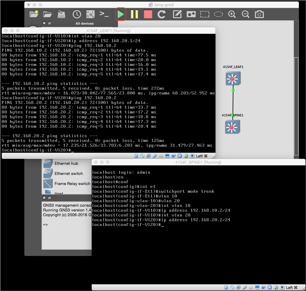
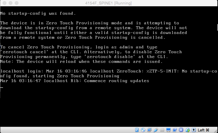
At this point we should have everything we need to verify functionality of ZTP - it’s the moment of truth.  Use the erase startup-config command followed by reload now to reload the vEOS instance with no startup configuration, which will trigger ZTP:


What we want to see is a successful DHCP process followed by the switch pulling down it’s basic config file and then rebooting:


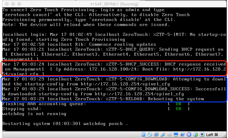
So in this case, the vEOS instance was assigned a temporary IP of 172.16.128.100 from the pool, which allowed it to reach the file server at 172.16.128.254 to download its configuration file before finally rebooting.  Once the instance finishes rebooting, we can verify that ZTP was successful simply by the fact we can see the hostname and login banner:


Congratulations - you’ve just done your first automated “bare-metal” provisioning with ZTP!  Now you have a good reference config to work off of - just copy the spine1_cfg file as many times as needed for each vEOS instance, modify the appropriate fields (Mgmt IP address, hostname, etc.), and you’re good to go.  Don’t forget that you’ll also need to add the appropriate DHCP host configurations as well.

Creating a Dynamic Lab Environment with vEOS and GNS3 - Part I

GETTING STARTED

Preliminary Installation Setup

Install GNS3
Install VirtualBox
Get ahold of the .vmdk and aboot.iso files


It is recommended to install VirtualBox AFTER you install GNS3 to avoid problems with GNS3 detecting VirtualBox.


Go to www.arista.com, and go to Support > Software Download.  The two files you’ll want are the .vmdk file as well as the Aboot .iso file:


Creating the Management Network

To simulate an out-of-band management network, we will create a vboxnet interface, similar to a loopback interface, on our laptop.  This will also allow us to interact with our virtual machines via SSH, etc.


Open VirtualBox, go to Preferences, and click Network. Select “Host-only Networks”, and then click the NIC adapter image with a plus symbol on it to add a new host-only network if there isn’t one already:


Select your newly-created vboxnet and click the screwdriver icon to configure it:


We’re going to be using ZTP to provision our switches, so select “DHCP Server”, ensure “Enable Server” is unchecked, and then click OK:


Verify you have a new interface reflecting your vboxnet configuration:


SETTING UP vEOS

Creating a Base Image

You’ll want a nice, clean base image to create clones from.  


To begin, in VirtualBox, click New:


Give your base image a name.  Use the drop-down menus to set the Type to “Linux”, the Version to “Other Linux (64-bit)”, and then click Continue:


Set the memory allocation to 2048, and then click Continue:


Select “Use an existing virtual hard disk file”, select the .vmdk file you downloaded earlier, and click Create:


Our base image has been created, but now must be configured.  Select the new base image, and click Settings:


Click Storage, and then use the drop-down menu to set the second entry under “Controller: IDE” to IDE Secondary Master, then click the small CD icon and select the Aboot.iso file downloaded earlier


Click Network, select Adapter 1, ensure “Enable Network Adapter” is checked, and use the drop-down menu to select “Host-only Adapter”.  Ensure the Name is populated with the management network created in the previous section, use the drop-down menu to set the Adapter Type is set to “PCnet-FAST III”, and ensure that “Cable Connected” is checked. Click OK to save your changes:


Leave the rest of the Adapters alone - these will be configured for you by GNS3 later.


Verify your base image settings and launch the VM to verify it successfully boots:


TIP!
At this point, you have a decision to make.  You can either leave the base image as-is and configure everything on the clones that you will make, or if there’s something that will be configured on every clone, such as a username, you could configure this in your base image so that you won’t have to do it on your clones.  For our lab though, we’re going to be provisioning everything with ZTP and Ansible, so I’m going to leave the base image as raw as possible. If you noticed, we created a host-only adapter in our base image so that every time we create a clone, it will already have its first adapter be its management connection.  You’ll see why later.


Creating Clones

If you haven’t already, shut down your base image.  Now, in VirtualBox, right-click it and select “Clone”.  Click “Expert Mode” - because you’re clearly too awesome for that guided nonsense (And doing it this way is just quicker).  Give your clone a name, ensure that “Full Clone” and “Reinitialize the MAC address of all network cards” is selected, and then click Clone - repeat as necessary to create additional clones:


WARNING!
This part is very important.  If you select “Linked Clone”, your clone will be linked to the base image instead of creating its own file.  This means if you accidentally choose to delete all files when you delete your clone later, it will also effectively delete your base image as well.  

If you do not select “Reinitialize the MAC address of all network cards”, all clones will have the same MAC address as your base image, and you can imagine the fun that will create in your virtual network.


GETTING STARTED IN GNS3

Adding VMs to GNS3

GNS3 has very tight integration with VirtualBox.  As you create connections between your vEOS instances, server VMs, etc., GNS3 takes care of all configuration needed on your VirtualBox VMs for you - no manual configuration needed inside of VirtualBox itself for each new connection.  


To get started, we’ll need to add our newly-minted cloned vEOS instances to GNS3.  Open GNS3, start a new project, and then open Preferences.  Go to VirtualBox > VirtualBox VMs, click New, use the drop-down menu to select your newly-created clones, and then click Finish - repeat as necessary:


Select your VM and click Edit. Under “Network”, configure the following and then click Ok, repeating as necessary for each VM:


NOTE
At the time of this writing, VirtualBox can support a maximum of 8 adapters.  Refer to the article in “Resources/Recommended Reading” for details.  The first adapter will be your management interface, hence the “First port name:”, and then you’ll have an additional 7 interfaces to play with.


TIP!
If you want your VM to cosmetically appear more like a switch in GNS3, under “General Settings”, set the Category to “Switches”, and change the Symbol to “Multilayer Switch”.


Click Apply, and then click OK to exit.


Now that our vEOS VMs are configured in GNS3, we can start building our virtual network. On the main project screen, click “Browse All Devices”, and then drag-and-drop your VMs onto the topology panel (the center panel):


Click “Add a Link”, click one VM, select “Ethernet1”, and connect it to your other VM on the same interface:


Click “Start/Resume all devices”, and when the VMs are finished booting, setup some VLANs and SVIs and verify you have connectivity:


Great!  Let’s move on to providing “bare-metal” provisioning with ZTP.

Monday, September 21, 2015

How Rapid Spanning Tree Protocol (RSTP) Handles Topology Changes

For this exploration I'm using Arista's Virtual Extensible Operating System (vEOS) version 4.15.0F running in GNS3(Which is pretty awesome).  The virtual switches have been configured in rapid-pvst mode.

Here is the topology:


EtherSwitches have been added only to capture traffic off monitoring sessions set up on Switch1 and Switch2 to look at in Wireshark.  The Ubuntu server can be ignored for the purposes of this blog entry.

Only VLAN 1 is present on all switches and Switch1 is configured to be the primary root, while Switch2 is configured to be the secondary. Here's the current state of the network:


First it's important to note that only a single thing will trigger a topology change event - the transition of a non-Edge port from a non-Forwarding to a Forwarding state. Why?  Because this newly Forwarding port could possibly provide a better path to a given destination MAC address than there was before, and the CAM table will need to be updated to reflect that and prevent the same MAC being displayed on more than one port.  It sounds strange that a loss of a Forwarding port doesn't trigger a topology change event, but think about it - in a L2 world, you can't have multiple paths to reach a destination. "There can be only one."  Otherwise it would likely mean there is a loop.  Taking that into consideration, if our only path to a destination MAC breaks, we know we can't get there unless another path is created by another port transitioning to Forwarding - which will trigger a topology change event.  Viola - work smarter not harder!

To review the Topology Change process when a switch detects a topology change event:
  1. Set tcWhile timer on all non-Edge Designated ports and Root port if it exists
  2. Flush MAC addresses learned on ports in step 1
  3. Send BPDUs with the Topology Change (TC) flag set on these ports every Hello seconds until tcWhile expires
So let's first look at what happens locally on a switch, as we shut interface Et1 on Switch4 which is its Root Port.  First, I'll ping Switch4 from Switch2, then look at Switch4's CAM table:

Switch4#sh mac address-table 
          Mac Address Table
------------------------------------------------------------------

Vlan    Mac Address       Type        Ports      Moves   Last Move
----    -----------       ----        -----      -----   ---------
   1    0800.274a.33f1    DYNAMIC     Et1        1       0:00:25 ago
Total Mac Addresses for this criterion: 1

We see it learned Switch2's MAC address on Et1. Vice-versa, we look at Switch2's CAM table and see it learned Switch4's MAC on Et1:

Switch2#sh mac address-table
          Mac Address Table
------------------------------------------------------------------

Vlan    Mac Address       Type        Ports      Moves   Last Move
----    -----------       ----        -----      -----   ---------
   1    0800.277b.3066    DYNAMIC     Et1        1       0:00:28 ago
Total Mac Addresses for this criterion: 1

Now, let's do the same process over again, but then shut down Et1 on Switch4. Et1 is Switch4's Root Port, so what should happen is Et2, which is an Alternate Port, should transition to a Forwarding state.  This meets the criteria for a topology change event.

After we shut Et1, we take a look at the spanning tree status on Switch4:

Switch4#sh span
VL1
  Spanning tree enabled protocol rapid-pvst
  Root ID    Priority    4097
             Address     0800.2773.3845
             Cost        4000 (Ext) 0 (Int)
             Port        2 (Ethernet2)
             Hello Time  2.000 sec  Max Age 20 sec  Forward Delay 15 sec

  Bridge ID  Priority    32769  (priority 32768 sys-id-ext 1)
             Address     0800.277b.3066
             Hello Time  2.000 sec  Max Age 20 sec  Forward Delay 15 sec

Interface        Role       State      Cost      Prio.Nbr Type
---------------- ---------- ---------- --------- -------- --------------------
Et2              root       forwarding 2000      128.2    P2p                     
Et3              alternate  discarding 2000      128.3    P2p

Et2 transitioned to a Root role, Forwarding state, which qualifies as a topology change event. Looking at the CAM table of Switch4, we see the previous entry is now gone:

Switch4#sh mac address-table 
          Mac Address Table
------------------------------------------------------------------

Vlan    Mac Address       Type        Ports      Moves   Last Move
----    -----------       ----        -----      -----   ---------
Total Mac Addresses for this criterion: 0

Looking at Switch2, we see the previous entry is also gone as well:

Switch2#sh mac address-table 
          Mac Address Table
------------------------------------------------------------------

Vlan    Mac Address       Type        Ports      Moves   Last Move
----    -----------       ----        -----      -----   ---------
Total Mac Addresses for this criterion: 0

Why did this also happen on Switch2?  If you scroll back up and look at what happens on a switch during a topology change event, you saw that the last item mentioned sending BPDUs with the TC flag set:
Send BPDUs with the Topology Change (TC) flag set on these ports every Hello seconds until tcWhile expires
So once Switch4 detected the topology change, it started firing off BPDUs with the TC flag bit set out its newly-elected Root Port, interface Et2.


Once a switch experiences a local topology change, or learns about one from another switch by receiving a BPDU with the TC flag set on a Root or Designated port, it too will in turn go through the same process.  So let's take a look at what happened on the network holistically:


  1. Interface Et1 which was the Root Port for Switch4 is shut down. Switch4 had elected Et2 as an Alternate Port previously, so it immediately transitions the port to the new Root Port. This places Et2 into a Forwarding state which triggers a topology change event, so Switch4 then sets the tcWhile timer and flushes the CAM table entries learned on Et2, and begins sending BPDUs with the TC flag set out the same port. At the same time, Et3 begins receiving superior BPDUs so it is transitions from a Designated Port to an Alternate Port.   
  2. Switch2 receives a BPDU with the TC flag set on Et4, so it sets the tcWhile timer, flushes any CAM table entries learned on, and begins sending BPDUs with the TC flag set on its Root and other Designated Port, Et1 and Et3, respectively. Ultimately, the TC BPDU sent from Et3 will be discarded upon reaching Switch3.
  3. Switch1 receives a TC BPDU on Et2.  It sets the tcWhile timer, flushes learned CAM table entries, and sends TC BPDUs from its only other remaining active Designated Port, Et5.
  4. After interface Et1 on Switch4 was shut down, Switch3 began receiving what it determined to be inferior BPDUs on Et4 due to Switch4 now advertising a higher Root Path Cost (RPC), so Switch3 transitioned the port from an Alternate Port to a Designated Port. Switch3 then receives a TC BPDU on Et1, so it sets the tcWhile timer, flushes any learned CAM table entries, and sends TC BPDUs out its only other Designated Port, Et4 - which will end up being discarded.
At this point, all switches have been informed and made the appropriate changes into a new, loop-free converged topology.  So that's how the topology change process is handled in RSTP!